How to create a hemicord mask?

Dear SCT team,

I’m hoping that there is a simple answer to this question, preferably one that includes “just use sct_create_hemicord”? :smiley:

I could use sct_get_centerline and then find the r/l coordinate of the centre point per-slice and then use this with something like fslmaths to zero anything up to or > than this value in the corresponding section of my _seg.nii.gz file, but that would probably be quite messy and involve some scripting…

If there’s nothing out there I’ll write it and share it, but I’d rather not reinvent the wheel, especially since mine will be made of stone and probably square.

Best wishes,

Jon

Hey Jon,

The most straightforward approach that comes to my mind would be to register your data with the template, and then either (i) use sct_extract_metric with lateral ROIs if you only need to quantify metrics within your mask or (ii) if you need actual masks to be used with your own processing routines, sum up atlas masks corresponding to each lateral ROIs. Example below:

# download example data
sct_download_data -d sct_example_data
sct_example_data/t2s
# segment cord
sct_deepseg_sc -i t2s.nii.gz -c t2s -qc ~/qc
# create label assuming FOV is centered at C3/C4 disc
sct_label_utils -i t2s_seg.nii.gz -create-seg 15,4 -o label_c3c4.nii.gz
# Register to template using input image as reference (we want to avoid straightening due to the thick slices), algo centermassrot to account for rotations, and bsplinesyn algo on the segmentation with iter=5 to allow large and regularized deformations
sct_register_to_template -i t2s.nii.gz -s t2s_seg.nii.gz -ldisc label_c3c4.nii.gz -ref subject -param step=1,type=seg,algo=centermassrot:step=2,type=seg,algo=bsplinesyn,iter=5,slicewise=1,smooth=0 -qc ~/qc
# warp template and atlas
sct_warp_template -d t2s.nii.gz -w warp_template2anat.nii.gz -a 1

At this point, you need to modify the created file label/atlas/info_label.txt to add custom labels corresponding to hemi-cord, by adding the following lines in the # Combined labels section:

56, left hemi-cord, 0,2,4,6,8,10,12,14,16,18,20,22,24,26,28,30,32,34
57, right hemi-cord, 1,3,5,7,9,11,13,15,17,19,21,23,25,27,29,31,33,35

Also see example here: info_label.txt (2.9 KB)

Then, you can use these combined labels to quantify stuff in each hemi-cord:

# quantify metrics on the left side of the cord
sct_extract_metric -i t2s.nii.gz -l 56,57

The beauty of this approach versus the R/L section of a segmentation based on the centerline in an FOV coordinate system, is that here the hemi-cord is derived from the registered mask, meaning that the R/L is defined slicewise relative to the cord orientation. Consequently, if the cord is slightly rotated, the output hemi-mask will “truly” be the hemi section of the cord (not a vertical cut which assumes the medial plane of the cord axis is aligned with the sagittal plane of the image).

If you wish to output physical hemi-cord masks (i.e., not use sct_extract_metric), you can generate those as follows:

sct_maths -i label/atlas/PAM50_atlas_00.nii.gz -add $(for i in `seq -w 2 2 34`; do echo "label/atlas/PAM50_atlas_${i}.nii.gz"; done) -o PAM50_atlas_left.nii.gz
sct_maths -i label/atlas/PAM50_atlas_01.nii.gz -add $(for i in `seq -w 3 2 35`; do echo "label/atlas/PAM50_atlas_${i}.nii.gz"; done) -o PAM50_atlas_right.nii.gz

Result looks like this:
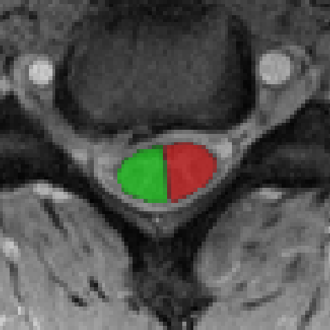
54

1 Like

That’s great - thanks. I would have ended up making a [pig’s ear | dog’s dinner | mess] of this I’m sure…

We’re looking at T1-weighted scans and had already done most of the registration so this should be relatively straightforward.

Best wishes,

Jon

Hi Julien,

Just a quick question - is there a quick way to have sct_extract_metric output csa for each hemicord and vertebral level separately? Currently it outputs the total number of voxels (in fact it’s non-integer) in each mask/vertebral level, which is a little awkward to convert to mean csa for a vertebral level (need to multiply by pixel csa and divide by number of slices - not that difficult, but … ).

It seems like the option to use labels (-l) was removed (?) from sct_process_segmentation, otherwise I could just use that.

Best wishes,

Jon

Hi Jon,

You can output CSA per vertebral level using the following command:

sct_process_segmentation -i PAM50_atlas_left.nii.gz -p csa -vertfile label/template/PAM50_levels.nii.gz -vert 2:5 -perlevel 1

Here is the output: csa.csv (955 Bytes)

HI Julien,

Yep - we’ve been doing that, but what I’d like is the CSA per hemicord per level…is that possible?

Cheers, Jon

hum, I might be misunderstanding what you are trying to get, but the following command does indeed output CSA for each hemicord (below is an example with the left hemicord created earlier in this thread), aggregated per vertebral level: C2, C3, etc.

sct_process_segmentation -i PAM50_atlas_left.nii.gz -p csa -vertfile label/template/PAM50_levels.nii.gz -vert 2:5 -perlevel 1

Hi Julien,

Sorry you’re right - I should have read more carefully - I missed the image output at the end.

Thanks for all your help!

Jon

Hi Julien,

We’re trying to understand the output from the commands you sent - in particular why they seem to generate data that is inconsistent with using the whole cord as input. i.e. right hemi + left hemi ≠ whole cord

We have two groups of subjects, which we put through the SCT pipeline to the point where we had segmented the cord on the structural images of both groups. We then put all the data through sct_process_segmentation (after remembering to run sct_warp_template first!), outputting csa per level for vert 3:8.

sct_process_segmentation -i sanlm_structural_seg.nii.gz -p csa -vert 3:8 -perlevel 1 -o csa_perlevel.csv

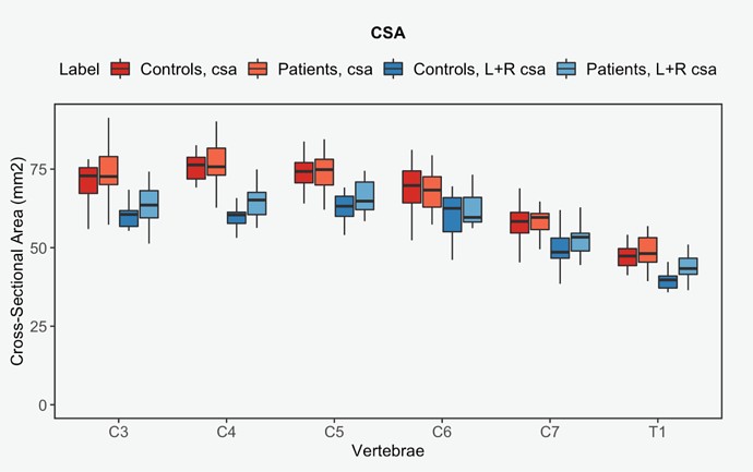
This showed that the cords were similar in csa between groups for all vertebral levels (and nicely demonstrate the expected increase around the cervical enlargement). See red/pink on attached graph.

We were then interested to see if the two hemicords were different in size at different vertebral levels (hence this thread). When we go through the steps above, we end up running sct_process_segmentation on a hemicord image that is derived from warping the template into the subject space and outputting separate csa for the left and right hemicords at different vertebral levels. See your code in previous responses.

The problem is that when we add the two values (for right+left) and compare between the two groups/per vertebral level (light/dark blue on attached graph), we get a different result to the original one when using the whole cord, with there now being apparently significant difference between csa at different levels for the two groups.

Any idea what might be going on?

Best wishes,

Jon

Hi Jon,

The following could explain discrepancies:

  • Computing cord CSA directly on the segmentation vs. CSA L/R on the PAM50 warped to the native space. If the registration fails, that would lead to large discrepancies. To address that issue, I would compare CSA_L + CSA_R with CSA computed on label/template/PAM50_cord.nii.gz.
  • When computing CSA corrected for angulation, it is possible that the curve fitting is highly inaccurate on the hemi cord, yielding large differences in angle estimation. To address that issue, you could run sct_process_segmentation with the flag no-angle 1 and see if you get more consistent results. In principle of course, angle should be taken into account.

If you cannot explain the discrepancies by any of the points above, I would be happy to look at your data. For convenience, you could share the data along with the code that leads to these results so I can replicate on my end and start debugging from there.

Best,
Julien

Hi Julien,

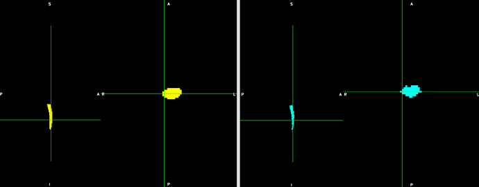
Sorry for the delay in replying. I’ve supplied some more details about our pipeline below, but in essence I think the problem is captured in this image:

On the left is the output from sct_deepseg_sc (from our structural scan), on the right is the result of registering the template to the structural scan. The registered PAM50_cord image is smaller and a bit more “scruffy” :wink: That’s the reality of our noisy T1 structural. This could easily account for differences?

I’m running the analysis you suggested (I think) two different ways with:
(1) sct_extract_metric -i ./fulllabel/template/PAM50_cord.nii.gz -f ./fulllabel/atlas -l 50,56,57 -perlevel 1 -vert 3:8 -o csa_perlevel_template.csv

and

(2) sct_process_segmentation -i PAM50_atlas_left.nii.gz -p csa -vertfile label/template/PAM50_levels.nii.gz -vert 3:8 -perlevel 1 -o csa_perlevel_left.csv
sct_process_segmentation -i PAM50_atlas_right.nii.gz -p csa -vertfile label/template/PAM50_levels.nii.gz -vert 3:8 -perlevel 1 -o csa_perlevel_right.csv
sct_process_segmentation -i label/template/PAM50_cord.nii.gz -p csa -vertfile label/template/PAM50_levels.nii.gz -vert 3:8 -perlevel 1 -o csa_perlevel_wholecord.csv

Once that’s done I’ll repeat method (2) with -no-angle 1 to assess the impact of angulation.

Does that sound about right?

Best wishes,

Jon

Registration pipeline details…

Just to check/take stock: we’re happy with the cord segmentation, we supplied manual labels for the intervertebral discs, then used:
sct_label_vertebrae -i sanlm_structural.nii.gz -s
sanlm_structural_seg.nii.gz -c t1 -initlabel
sanlm_structural_labels_hand.nii.gz
(Checking sanlm_structural_seg_labeled.nii.gz shows a good correspondence between the labels and the anatomy)

followed by:
sct_label_utils -i sanlm_structural_seg_labeled.nii.gz -vert-body 3,8
-o sanlm_structural_seg_labels_vert.nii.gz

The second command creates only the mid-vertebral level labels for vertebra 3 and 8, used in registration to template:

sct_register_to_template -i sanlm_structural.nii.gz -s sanlm_structural_seg.nii.gz \
			-l sanlm_structural_seg_labels_vert.nii.gz -c t1 -ref template -param \
			step=1,type=seg,algo=centermass:step=2,type=seg,algo=syn,slicewise=1,smooth=0,iter=5:step=3,type=im,algo=syn,slicewise=1,smooth=0,iter=3

Afterwards I ran the sct_warp_template command to bring the template over to the structural.

Loading labels/PAM50_levels.nii.gz and sanlm_structural_seg_labeled.nii.gz shows some small differences between the template’s vertebral levels and the more manually drive ones, but nothing disastrous.

So I’m fairly confident the the sct_process_segmentation should have worked as expected - when using sanlm_structural_seg.nii.gz as the input, and reporting the csa metric.

Hi Jon,

A couple of things:

The “scruffy” appearance of the right image is (imho) likely more related to the nearest neighbour interpolation than to issues in registration. Which is why it is quite important to use linear interpolation when you plan to compute CSA. This is done by default by sct_warp_template for all images under label/atlas/, but not for label/template/PAM50_cord.nii.gz. So, two things you could do (there might be typos-- i haven’t tested the code below):

  1. Warp the cord template using linear interpolation, then compute CSA:
sct_apply_transfo -i $SCT_DIR/data/PAM50/template/PAM50_cord.nii.gz -d sanlm_structural.nii.gz -w warp_template2anat.nii.gz -x linear
sct_process_segmentation -i PAM50_cord_reg.nii.gz -p csa -vertfile label/template/PAM50_levels.nii.gz -vert 3:8 -perlevel 1 -o csa_perlevel_whole-cord-registered-linear.csv
  1. Sum the right and left masks, then compute CSA:
sct_maths -i PAM50_atlas_left.nii.gz -sum PAM50_atlas_right.nii.gz -o PAM50_atlas_left-right.nii.gz
sct_process_segmentation -i PAM50_atlas_left-right.nii.gz -p csa -vertfile label/template/PAM50_levels.nii.gz -vert 3:8 -perlevel 1 -o csa_perlevel_left-right.csv

Regarding the registration pipeline: since you are already doing manual labels to initialize sct_label_vertebrae, why not simply bypassing this function and directly create two labels (e.g., mid-vertebrae at C3-T1) using sct_label_utils -create-viewer?

Cheers
Julien

Hi Julien,

Thanks again for your input! Only one typo → -sum = -add

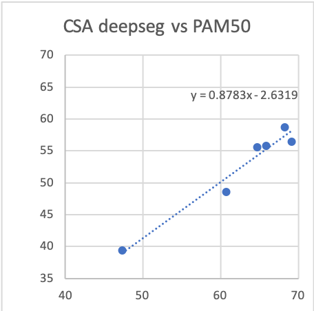
The linear interpolation definitely makes the cord outline look more like the one determined using deepseg, but the absolute values estimated using sct_process_segmentation are still quite different. Sorry for the nasty excel graphs…

CSA_linear_interp

When using the PAM50 cord registered to the structural it consistently underestimates CSA compared to that from the output of deepseg. The registration looks really go though…

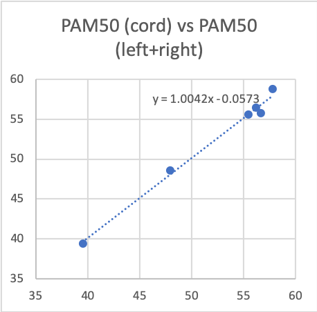
However, it (PAM50_cord in structural space) is internally consistent with the sum of the left right masks…

CSA_linear_left_right

Which brings us full circle. We wanted to know whether the asymmetry we saw when using sct_extract_metric on the output from deepseg, could be validated against the the cross sectional areas estimated for the left and right cord, but given the difference in results with either method I’m not sure what to conclude…

Cheers, Jon

Right. I’m not surprised there is a systematic bias in the registered template, which is related to the interplay between the registration metric (CC/MI/MeanSquares), algo (SyN/BsplineSyN/other), number of steps, gradStep, smoothing, type of image (im/seg), etc. You could spend days playing with those parameters trying to minimize this bias. Bottomline is that, this bias is likely systematic, meaning that it (almost) equally applies to the right and left side of the cord, therefore if you find an asymmetry using the output of sct_deepseg_sc, it is likely that you would find the same relative asymmetry for the output of sct_process_segmentation on the left/right hemi cords. Hope that makes sense!