Dear SCT team,
Thank you for your time!I have used ‘sct_register_to_template’ and ‘sct_register_multimodal’ to register t2s to the PM50 template. At the same direction,the t2s image has less slices than the template. How does SCT generate the slices that don’t exist in the t2s image? During the regiatration,do all slices of the t2s image generate the same amount of slices? These questions is so important for my research.Looking forward to your reply.Thanks!
I use these command:
sct_register_to_template -i t2.nii.gz -s t2andt2s_seg.nii.gz -l t2andt2s_labels_vert.nii.gz -c t2 -qc ~/qc_singleSubj
sct_register_multimodal -i ${SCT_DIR}/data/PAM50/template/PAM50_t2s.nii.gz -iseg ${SCT_DIR}/data/PAM50/template/PAM50_cord.nii.gz -d t2s.nii.gz -dseg t2s_seg.nii.gz -param step=1,type=seg,algo=centermass:step=2,type=seg,algo=bsplinesyn,slicewise=1,iter=3:step=3,type=im,algo=syn,slicewise=1,iter=1,metric=CC -initwarp warp_template2anat.nii.gz -initwarpinv warp_anat2template.nii.gz -owarp t2s2temp/warp_template2t2s.nii.gz -owarpinv t2s2temp/warp_t2s2template.nii.gz -ofolder t2s2temp/
Hi @janessa:
This is a very good question! Thank you for asking. 
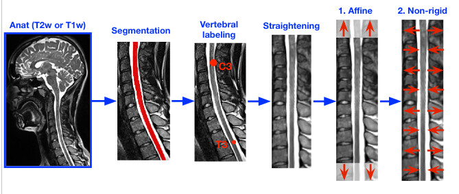
I notice that you are using the default parameters for the sct_register_to_template command. Template registration involves a number of steps:
- Straightening
- Affine transformation
- Non-rigid transformation
This can be seen in the following figure:

As shown in the figure, the steps that are most relevant to your question are “1. Straightening” and “2. Affine transformation”, since both of these steps involve transformations that change the number of axial slices of the image.
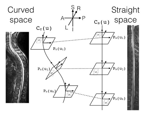
The straightening step uses a b-spline interpolation of the spinal cord centerline when computing the transformation between the curved and straight space. The full straightening algorithm is summarized here, and the process is shown in this figure:

However, this b-spline interpolation is entirely separate from the interpolation that gets used when the computed transformation is actually applied to the image.
Once the straightening transform is computed, it is saved as a warping field, then concatenated with the affine transformation from the second step using the ANTs tool ComposeMultiTransform. Then, this composite transformation is applied to the image using the sct_apply_transfo script. This script uses b-spline interpolation by default via the ANTs tool ApplyTransforms. (Note: The “spline” interpolation in sct_apply_transfo corresponds to the -n BSpline[3] (order=3) option in ANTs.)
In short: b-spline interpolation is used when applying the SI-axis transformations. (Though, it may also be worth noting in your research that b-spline interpolation is also used when actually determining the straightening transformation in the first place.)
Though, I’m just going to tag @jcohenadad, in case he has any additional input or if I have missed something.
Kind regards,
Joshua
If I understand correctly, you are registering T2*w scans which are axial with thick slices (eg: 0.5x0.5x3mm) to the PAM50 template which has isotropic resolution (0.5mm iso). So there is necessarily an interpolation that is required. Regardless if you do straightening or not. If you look at your T2*w scan in the PAM50 space, 0.5x0.5x3 voxels need to be transformed to 0.5mm iso voxels by interpolation

